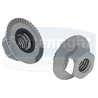
Hex Flange O-Ring Seal Nuts, typically in accordance with DIN 6923 / ISO 4161 / ASME B18.16.4, feature an “O” ring positioned in a groove on the underside of the nut – designed to provide 360° sealing protection against the elements.
These components ensure contaminants are unable to enter an application whilst preventing matter such as air and water from escaping. The O-ring can be supplied in various materials to offer different physical, chemical and mechanical properties. This includes the likes of Silicone rubber, Nitrile rubber (Buna-N), Fluorosilicone, EPDM, Viton, and many more.
Hex Flange O-Ring Seal Nuts arrive pre-assembled and ready to use, operating the same as conventional flanged hex nuts. During installation with a standard spanner, wrench or hex socket, the O-ring is compressed between the groove and mating surface whilst ensuring metal on metal contact for a tight and secure seal.
They are often selected for high pressure or contamination-free environments – widely utilised in the aerospace, medical, and food industry as a result. Other uses include within military equipment, as well as applications with the strictest sealing requirements.
Typically manufactured from A2 / 304 Stainless Steel and A4 / 316 Stainless Steel, Hex Flange O-Ring Seal Nuts are available with a smooth or serrated flange, where the additional serrations create a locking mechanism that increases vibration resistance.
Hex Flange O-Ring Seal Nuts are tailor made to meet your requirements – manufactured to order in a wide range of sizes, materials and finishes. Minimum order quantities apply.
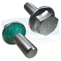
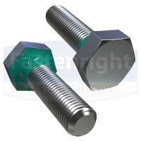
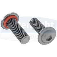
Fastenright supply various types of Sealing Fasteners suitable for the most demanding applications and assemblies.
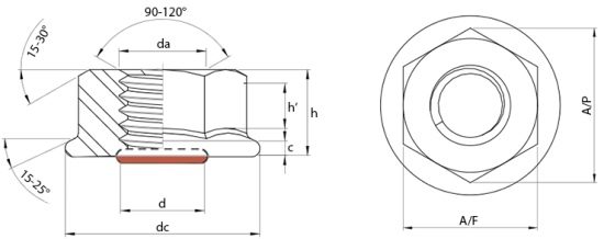
| DIN 6923 Technical Data & Availability | |||||||||||||||
| Thread Diameter (d) |
M3 | M4 | M5 | M6 | M8 | M10 | M12 | M16 | |||||||
| dc max. (mm) | 8 | 10 | 11.8 | 14.2 | 17.9 | 21.8 | 26 | 34.5 | |||||||
| h max. (mm) | 4 | 4.5 | 5 | 6 | 8 | 10 | 12 | 16 | |||||||
| h’ min. (mm) | 1.7 | 1.9 | 2.2 | 3.1 | 4.5 | 5.5 | 6.7 | 9 | |||||||
| A/F max. (mm) | 5.5 | 7 | 8 | 10 | 13 | 15 | 18 | 24 | |||||||
| Size not listed? Please make an enquiry – we may be able to provide it. | |||||||||||||||
| ASME B18.16.4 UNC / UNF Technical Data & Availability | |||||||||||||||
| Thread Diameter (d) | 6-32 UNC |
8-32 UNC |
10-24 UNC |
10-32 UNF |
12-24 UNC |
1/4-20 UNC |
1/4-28 UNF |
5/16-18 UNC |
5/16-24 UNF |
3/8-16 UNC |
3/8-24 UNF |
1/2-13 UNC |
1/2-20 UNF |
||
| dc max. (in) | 0.422 | 0.469 | 0.5 | 0.5 | 0.594 | 0.594 | 0.594 | 0.68 | 0.68 | 0.75 | 0.75 | 1.031 | 1.031 | ||
| h max. (in) | 0.171 | 0.203 | 0.219 | 0.219 | 0.236 | 0.236 | 0.236 | 0.283 | 0.283 | 0.347 | 0.347 | 0.458 | 0.458 | ||
| h’ min. (in) | 0.1 | 0.13 | 0.13 | 0.13 | 0.14 | 0.14 | 0.14 | 0.17 | 0.17 | 0.23 | 0.23 | 0.31 | 0.31 | ||
| A/F max. (in) | 0.312 | 0.344 | 0.375 | 0.375 | 0.438 | 0.438 | 0.438 | 0.5 | 0.5 | 0.562 | 0.562 | 0.75 | 0.75 | ||
| Size not listed? Please make an enquiry – we may be able to provide it. | |||||||||||||||


 Next: Double End Studs (DIN 939)
  Prev: Cap Head Seal Screws with Under Head Seal