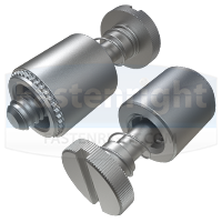
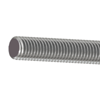
Slotted Spring-Loaded Self Clinch Captive Panel Fasteners are designed for mounting on thin sheet metal panels in order to provide fastening hardware.
These components are mounted onto a panel by applying sufficient squeezing force, typically using a press. The panel material is displaced and forced into the undercut and around the knurled self-clinch feature.
This ensures that the fastener remains captive within the panel for easy installation and removal of components, whilst preventing damage to an assembly due to loose hardware. They are available in two materials:
Steel Slotted Spring-Loaded Self Clinch Captive Panel Fasteners:
- The screw is made from Carbon Steel with a Nickel plated finish, the retainer is made from Hardened Carbon Steel with a Nickel plated finish, and the spring made from 300 Series Stainless Steel.
- Both the screw and retainer can be supplied with a Black nitride finish on request.
- For use in sheet hardness HRB 80 or less on the Rockwell B scale, or HB 150 or less on the Brinell scale.
Stainless Steel Slotted Spring-Loaded Self Clinch Captive Panel Fasteners:
- The screw, retainer and spring are made from 300 Series Stainless Steel, with the screw and retainer hosting a Passivated finish.
- Both the screw and retainer can be supplied with a Black nitride finish on request.
- For use in sheet hardness HRB 70 or less on the Rockwell B scale, or HB 125 or less on the Brinell scale.
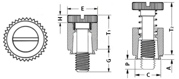
The screw features a knurled edge for improved grip, as well as a slot drive for installation with a standard slotted screwdriver.
Available at Fastenright in thread sizes M3 to M6 with multiple screw lengths. #4 to 1/4″ Unified threads can also be supplied.
| Metric Technical Data & Availability | |||||||||||||||
| Thread Diameter | M3 | M4 | M5 | M6 | |||||||||||
| A max. (mm) | 1.53 | 1.53 | 1.53 | 1.53 | |||||||||||
| Min. Sheet Thickness (mm) |
1.53 | 1.53 | 1.53 | 1.53 | |||||||||||
| C max. (mm) | 6.71 | 7.9 | 8.72 | 10.47 | |||||||||||
| Sheet Hole Size (mm) + 0.08 |
6.73 | 7.92 | 8.74 | 10.49 | |||||||||||
| E (mm) ± 0.25 |
7.92 | 9.53 | 10.31 | 11.89 | |||||||||||
| G (mm) ± 0.4 |
6.4 | 9.5 | 7.9 | 11.1 | 14.3 | 7.9 | 11.1 | 14.3 | 9.5 | 12.7 | 15.9 | ||||
| H (mm) ± 0.13 |
1.83 | 2.08 | 2.08 | 2.46 | |||||||||||
| P (mm) ± 0.64 |
0 | 3.2 | 0 | 3.2 | 6.4 | 0 | 3.2 | 6.4 | 0 | 3.2 | 6.4 | ||||
| T1 max. (mm) | 9.14 | 11.43 | 11.47 | 14.73 | |||||||||||
| T2 nom. (mm) | 13.72 | 17.53 | 17.53 | 22.35 | |||||||||||
| Min. Dist. Hole C/L to Edge (mm) |
6.35 | 7.87 | 8.63 | 9.65 | |||||||||||


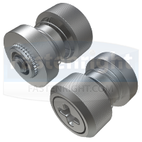
 Next: Phillips Recessed Head Self Clinch Captive Panel Fasteners
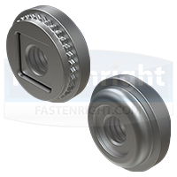
  Prev: Spring-Loaded Locating Pin Captive Panel Fasteners